GET IN TOUCH NOW
Our Advantages
Please fill out our inquiry form and one of our specialists willbe right with you!
Contact us
p-i-1.webp
home-8.webp500
die-5.webp
Material
die-5.webp
Application diagram
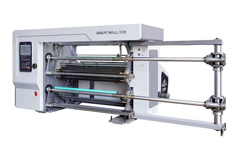
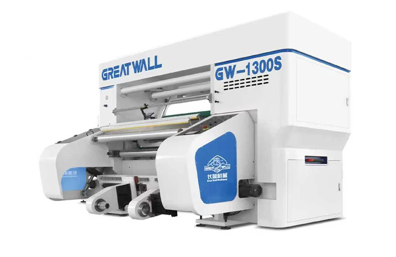
High-Speed Slitting Machine for Coated Paper, Films & Specialty Materials >

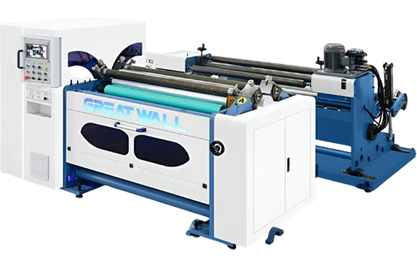
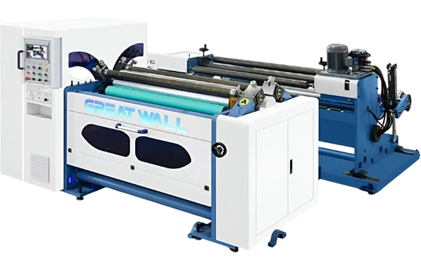
GW-1300S Servo High-Speed Slitting Machine for Coated Paper, Films & Specialty Materials applies  to slit cellophane, PET, OPP, CPP, PE, PVC and computer security labels, electronic computers, optical materials, film roll, and foil roll, all kinds of paper rolls, film and printing of various materials. , etc.

  • Servo controlled
  • Applies to slit cellophane
  • High Speed
p-i-1.webp
home-8.webp600
die-5.webp
Material
die-5.webp
Application diagram
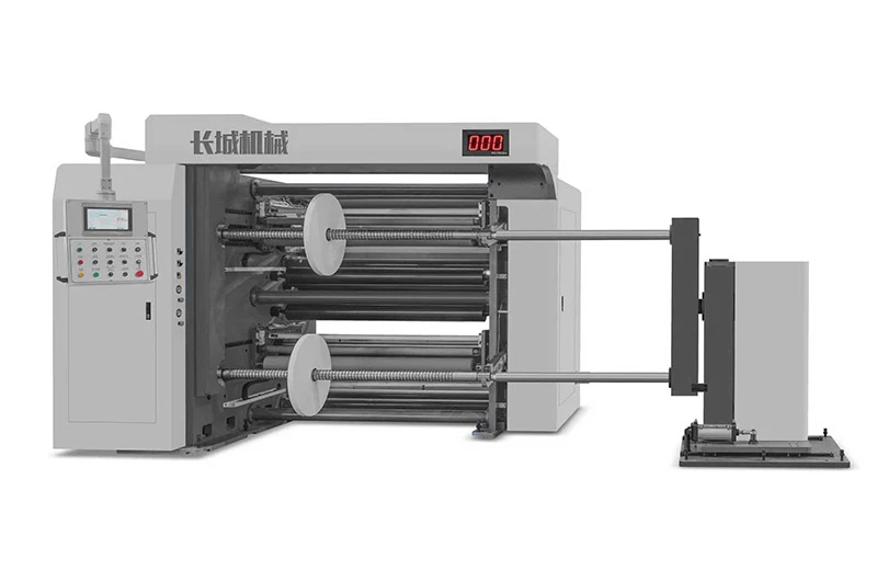
Label Slitting Rewinding Machine >

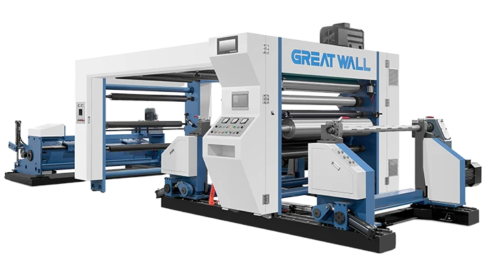
GW-1700L series is suitable for slitting and rewinding large roll materials, especially for composite paper, coating paper, self-adhesive label paper.

  • PLC control
  • Frequency conversion speed regulation
  • Double slip axis shaft

Heavy-Duty Metal Coil Slitting System

  • Robust Structural Design - High-rigidity frame and alloy blades enable stable slitting of metal coils from 0.1mm to 3.0mm thickness.
  • Burr-Free Cutting - Optimized blade angle and gap control ensure smooth, clean cut edges without burrs.
  • Intelligent Lubrication System - Equipped with circulating cooling and automatic lubrication to reduce blade wear and extend service life.
GREAT WALL One-Stop Packaging Solution
With nearly 40 years of professional experience, we focus on core industries to provide you with end-to-end equipment and complete production line solutions from materials to finished products, ensuring efficient and stable production.
Get your customized solution now
home-24.webp
Label slitting machine FAQ
Roll die cutting machine in the South China Printing 2021
How is the pla paper cup produced by the disposable paper cup manufacturer?

How is the pla paper cup produced by the disposable paper cup manufacturer? It turned out to be done in this way

Disposable paper cups are an item in our lives. When we entertain guests, we often use disposable paper cups. Although paper cups are disposable products, we still don't know how disposable paper cups are produced. Let me briefly introduce how pla paper cups are produced.

Automatic High Speed Roll Die Cutting Machine

Disposable paper cup production process: base paper coating---cutting---typesetting---printing---film cutting---sterilization---forming---sterilization and packing---warehousing . The first is to deal with the width of the paper, which is determined according to the facing and method of the printing plate. Either slit or die cut, followed by printing. There are two types of printing: offset printing and kneading printing. The next step is die-cutting, which is to cut the printed paper into fan-shaped sheets. It should also be said that some advanced machines can die-cut by themselves. The last step is molding, which requires two parts: the cup body and the bottom of the cup.

There is a saying that disposable paper cups are easy to spread, that is, the inner layer of paper cups contains paraffin, which will melt when filled with hot water, and will be harmful to the body when deposited in the stomach. In fact, the disposable paper cups themselves are divided into two types: one is for "cold water cups", which is indeed waxy; the other is for "hot water cups", also known as film-coated cups, the inner wall is still a layer of polyethylene The melting point of PE-coated plastic film is much higher than that of wax, which is 80°C ~ 130°C, so compared with wax, it can be ideally used to hold hot beverages.

The so-called cup body is the fan-shaped piece that is die-cut at the front, and the bottom of the disposable paper cup is the paper rolls of different specifications cut out. Slitting [cross-cutting] printing, die-cutting, forming, there are 4 kinds of machines in the 4 processes, and there is an auxiliary resource in the operation of the 4 kinds of machines, that is, compressed air. The equipment includes; slitting machine, die-cutting machine, (prepress equipment: plate making, printing plate,) printing machine, paper cup forming machine.

The raw materials for making paper cups are super-large rolls of harder and slightly thicker paper rolls. Although the diameter of the paper roll is only 1 meter, the paper length is 5,000 meters, and the super-large roll with a weight of one ton can be made into 250,000 paper cups.

Automatic High Speed Roll Die Cutting Machine

A very simple example: I have mailed teaching materials after graduating from college. The density of books and paper is high, and the stacks are overweight, and the courier fee is astonishing... Therefore, the factory is generally directly computer-controlled for transportation, and there is very little manual handling. Effort is also prone to danger.

The production process of the disposable paper cup cold drink cup is direct printing, die cutting, molding processing, and spraying food wax on the surface of the paper cup base paper. The production process of the hot drink cup is that the paper cup base paper is coated into paper cup paper, printed, die-cut, and processed. Hot drink cups need to be coated, not waxed, because the heat may cause the wax to melt and be harmful to the body, that's the difference. The paper cup paper is printed with flexographic water-based ink. For raw paper, many paper manufacturers provide printing and die-cutting services, so when you first invest in the establishment of paper cups and paper bowls, you can directly buy the printed and die-cut paper cups. Because the cost of printing and die-cutting does not account for a small proportion of the cost in the production of paper cups and paper bowls, the cost is mainly determined by the size of the paper cup and the weight of the paper.

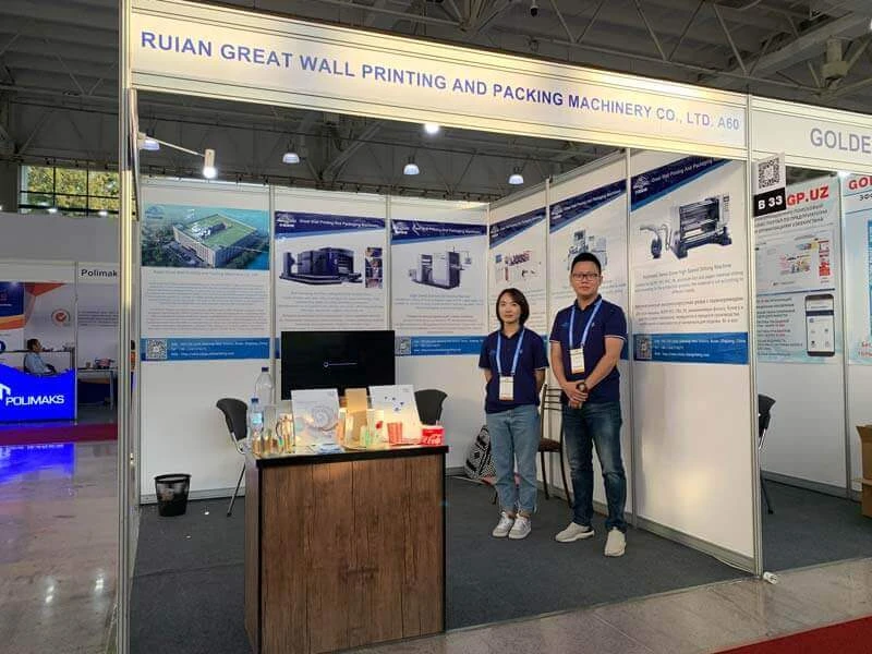
2019 O’ZBEKinPRINT

2019 O’ZBEKinPRINT , 9-11 October. 2019, Tashkent, Uzbekistan.

We joined the 21st International Exhibition of O’ZBEKinPrint in Tashkent. We found the market will be large in the future. We also visited our old customers in Uzbekistan  which bought our printing machine ,slitting machine before . and also gained many customers there.

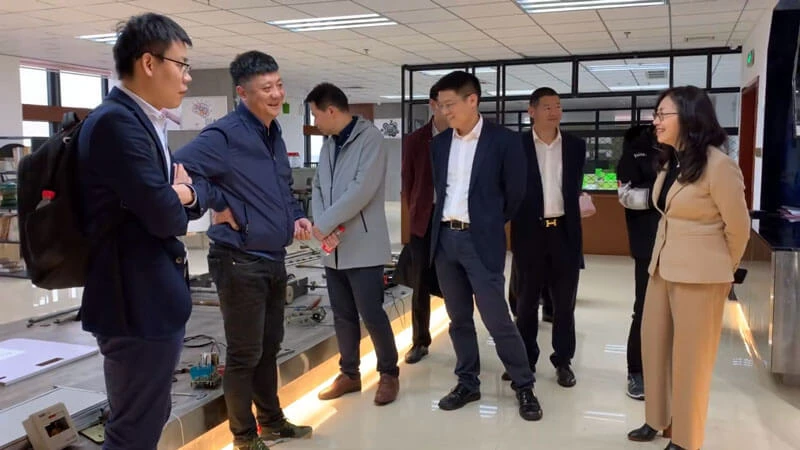
The academician of Chinese Academy of Science visit our company

Date of occurrence:March 3.15

The academician of Chinese Academy of Science and the city leaders visit our R&D Department, which was established with Ruian College of Wenzhou Vocational and Technical College in 2017. They discuss the present situation and prospect of the machinery.

How closed-loop tension systems stop thin web wrinkling during high-speed converting

Imagine you’re running a 12‑micron BOPP film at 400 meters per minute. The unwind roll is fresh, the coating station is dialed in, and then it appears — a fine lateral wrinkle snaking across the web, just before the winding drum. By the time you react, 800 meters of material are already crinkled into scrap. If this scene sounds familiar, you’re not alone. In thin‑film converting, wrinkling is the silent yield killer, and the culprit almost always traces back to tension control — or the lack of it.

Understanding why thin webs wrinkle requires stepping inside the converting process. Film is an elastic material; when tension distribution across its width becomes uneven, the web buckles to relieve stress. At high speeds, this instability triggers oscillation and permanent creasing. The root causes are manifold: slightly misaligned idler rollers, diameter‑build‑up on the rewind, inertia during acceleration or deceleration, and temperature fluctuations that alter material modulus. In an open‑loop system, the operator sets a nominal tension value, and the drive simply tries to hold a corresponding motor current. But open‑loop control cannot compensate for real‑time changes — friction variations in bearings, out‑of‑round rolls, or even air humidity that changes the coefficient of friction. As a result, the actual web tension can drift by 15–30%, creating ideal conditions for wrinkles. Industry surveys consistently show that improper tension contributes to over 70% of web‑related defects in thin‑film processing. The financial drain is staggering: lost raw material, machine downtime, and delayed shipments. That’s where a more intelligent approach becomes critical. Many converting shops have discovered that investing in advanced web tension management yields a rapid return through waste reduction alone.

The move from open‑loop to closed‑loop tension control fundamentally changes the equation. In a closed‑loop configuration, a sensor — typically a load cell, a dancer roller with a position transducer, or a strain‑gauge‑based tension amplifier — continuously measures actual web tension and feeds a signal back to the controller. The controller compares this feedback with the setpoint and instantly adjusts the torque command to the unwind brake or the motor drives. Modern systems execute this loop hundreds of times per second using PID algorithms, and the best ones automatically adapt gains based on line speed and roll diameter. For fragile films under 20 microns, this real‑time correction is not a luxury; it’s the difference between a perfectly flat roll and a crinkled mess.

Consider what happens during emergency stops or rapid speed changes. A roll with large inertia tends to over‑speed momentarily, creating a slack section that later snaps tight — the classic recipe for wrinkling. A closed‑loop dancer system absorbs that excess web mechanically and gives the drive a buffered correction window. Meanwhile, load‑cell‑based feedback can immediately reduce unwind torque, preventing the tension spike. Some converters are now adopting integrated closed‑loop converting systems that combine dancer feedback with load‑cell trimming to deliver both the fast mechanical response and the high precision of electronic control.

high-speed-servo-slitting-machine-for-filmstickers

Beyond instantaneous correction, closed‑loop architectures allow for sophisticated taper tension profiles during winding. As the roll diameter grows, the pressure exerted on inner layers increases exponentially, causing them to buckle and form “star‑shaped” or telescoped defects. A closed‑loop controller can smoothly reduce tension setpoint — often following a hyperbolic or linear taper — based on the real‑time diameter measured by a sensor. When this taper is tuned correctly, the roll builds with even hardness from core to outer wraps, virtually eliminating in‑roll wrinkling. For film slitting machines handling shrink‑sensitive substrates, this feature alone can boost first‑quality yield by 8–15%.

However, technology alone isn’t a silver bullet. I’ve seen plants where a high‑end closed‑loop system couldn’t stop wrinkling simply because a misaligned idler roll had been overlooked. The web doesn’t care how advanced the control algorithm is if it has to travel over a roller with 0.5° angular error. A holistic setup checklist should include: laser aligning all rollers within 0.1 mm/m parallelism, selecting proper roller surface coatings (such as plasma‑coated ceramic or textured rubber) that match the film’s coefficient of friction, verifying that load‑cell mounts are free of mechanical bind, and ensuring the controller’s filter settings aren’t masking real tension ripple. In one case, a converter improved wrinkle‑free running speed by 30% just by switching to a grooved idler that broke up the air boundary layer on a glossy film — a simple mechanical fix that multiplied the effectiveness of the electronic control.

A common pitfall is treating the unwind and rewind zones in isolation. Tension disturbances propagate: a sudden snatch on the unwind can travel through a coating nip and disturb a delicate lamination. That’s why forward‑thinking operations are now linking tension loops across the entire line, so that the rewind speed profile is dynamically skewed based on the tension readings from the process section. This coordinated control approach, often referred to as “cascaded tension master‑slave architecture,” is becoming standard in high‑speed lines running below 12‑micron films. If your current setup still relies on manually tuned potentiometers, it may be time to evaluate precision roll‑to‑roll finishing equipment that natively supports distributed tension control.

Preventive maintenance plays an often‑underestimated role in anti‑wrinkling. Load cell calibration should be verified at least every six months using a known weight or certified load rig. Dancer cylinders need consistent air pressure, free of moisture or oil contamination that causes stiction. Even the electrical noise from a nearby variable‑frequency drive can inject false ripple into the tension signal, so cable shielding and proper grounding should be checked during annual inspections. Document these checks; operators who see a trend of drifting sensor zero‑offset can intervene before wrinkles appear.

So, where does this leave the converter who wants to move from reactive firefighting to predictable, high‑speed production? The path is clear: start by auditing the mechanical condition of the web path, then layer in a true closed‑loop tension system capable of high‑speed digital communication and multi‑zone coordination. When such a system is properly implemented, the results are tangible — rolls that feel consistently dense to the knuckle‑tap, zero‑wrinkle edges under a microscope, and converting lines that run through shift changeovers without a hiccup.

If you are looking to bring this level of consistency to your own production floor, solutions that combine closed‑loop tension algorithms with rigid, vibration‑damped frame structures are worth exploring. Changcheng, for instance, has focused on developing Changcheng’s high‑performance converting solutions that integrate fast‑response tension control, automatic taper calculation, and user‑friendly recipe management — directly targeting the root causes of thin‑web wrinkling. Whether you’re running packaging films, battery separator, or optical sheet, the principle remains the same: what the web doesn’t feel, the operator won’t have to fix.

This article is based on general principles of web handling and tension control. Performance outcomes depend on specific material characteristics, machine condition, and operator practice. Always consult your equipment manufacturer for application‑specific guidance.

Roll Die Cutter vs Flatbed Die Cutter 

Every production manager in the label and packaging sector knows the moment of truth. You’ve just landed a contract for a new job—perhaps a run of 200,000 pressure-sensitive wine labels with intricate foil stamping, or a short-run tuck-top carton from heavy board. The artwork is locked in, the deadline is tight, but the nagging question remains: “Are we putting this on the right finishing system?” Misjudge your die cutting platform, and you’ll either bleed money through excessive tooling costs or watch your on-time delivery rate crumble under slow throughput.

The choice between a rotary and a flatbed die cutter isn’t about which technology is inherently “better.” It’s about which one aligns with the physical reality of your substrate, your run lengths, and your in-house skill set. Let’s clear the fog with a structured, application-first comparison.

The Core Principle: Intermittent vs. Continuous Motion

Before diving into metrics, it helps to visualize the fundamental working difference. A flatbed die cutter operates with an intermittent stop-start motion: the material feed pauses while a steel rule die descends vertically to kiss-cut or through-cut the stock. This mechanical simplicity gives it tremendous versatility in web width and material thickness, but it also creates a speed ceiling.

In contrast, a rotary system relies on a continuous motion principle—the web flows without interruption between a precision-ground magnetic or solid die cylinder and a hardened anvil roller. This architecture, often found in systems built around flexible magnetic cylinders, unlocks the speeds converters dream of but historically came with a cost premium on the tooling side.

Speed and Throughput: Where the Lines Blur

Let’s address the most common—and often misleading—spec on the datasheet. Flatbed presses typically quote mechanical speeds of 8,000 to 12,000 cycles per hour. In rotary converting, equivalent systems regularly run at 50 to 80 meters per minute, which on a press handling 200mm repeat lengths can translate to over 15,000 impressions per hour, with some high-end modular equipment reaching double that.

But here’s the nuance: raw strokes per minute mean nothing if job changeover eats your shift. Flatbed systems that use interchangeable chase frames can swap die sets in under 10 minutes. A magnetic cylinder-based web-fed machine can do it in under 90 seconds, without tools. If your typical order book contains dozens of short-run SKUs, that setup time differential quickly overwhelms the cruising speed advantage. It’s the multiplication of “time spent cutting” versus “time spent preparing to cut” that defines your true daily capacity. For operations where changeover agility is non-negotiable, many teams find that a modular rotary converting system designed for fast die changes becomes a clear productivity lever.

970mm-automatic-roll-stamping-and-die-cutting-machine

Substrate Flexibility: Who Handles the Tough Stuff?

Flatbed cutting holds a genuine edge when you deal with heavyweight substrates—think 400gsm board, corrugated liners, or materials with a tendency to crack under tight radius bends. Because the die hits the material while it’s stationary and flat, you can apply enormous tonnage and dwell time without worrying about web tension control or cylinder deflection.

Rotary technology, on the other hand, truly shines on thin, delicate, and extensible films. When you’re converting 30-micron BOPP, flexible packaging laminates, or unsupported PE, the continuous web path eliminates the acceleration-deceleration shocks that cause register drift and material distortion. An experienced operator once told me, “On a 12-micron PET liner, the flatbed system was producing ±0.2mm register; after we transitioned to a web-fed magnetic die cutting setup, we held ±0.1mm without breathing on the tension zone.” That’s not a machine specification—it’s a material physics limitation being bypassed. If your product mix is tilting decisively toward thin-gauge films and flexible packaging, evaluating equipment engineered for stable, high-tension web handling on delicate substrates is a logical next step.

Tooling Costs and the Breakeven Fallacy

A persistent myth in the industry is that flatbed tooling is “cheap” and rotary tooling is “expensive.” As with most things in manufacturing, the reality is volume-dependent. A flatbed steel rule die might cost $80–$300 depending on complexity, making it irresistible for prototyping and ultra-short runs. A solid rotary die, by contrast, could be $2,000+, and a flexible magnetic die might range from $150 to $800. But that comparison ignores two factors: longevity and repeat accuracy.

A quality flexible die can deliver 500,000 to over 1 million impressions before resharpening—flatbed rules wear faster, especially when kiss-cutting abrasive thermal labels. More importantly, when you reorder a flexible die from your supplier, you get a digitally manufactured clone of the original, guaranteeing that the cut geometry on this year’s repeat job matches last year’s setup perfectly. This repeatability is critical in pharmaceutical labels where fold lines and peel tabs must hit precise coordinates. The break-even calculator needs to count the cost of re-registration, make-ready waste, and operator tinkering, not just the invoice price of the tool.

Below is a summary table to guide your initial evaluation.

Feature Flatbed Die Cutter Rotary Die Cutter (Magnetic Cylinder)
Ideal Run Length 1–5,000 sheets/webs 5,000–1,000,000+ impressions
Substrate Sweet Spot Heavy board, carton stock, >250gsm Film, foil, labels, PE, ≤250gsm
Max Mechanical Speed ~8,000–12,000 cph Equivalent to 15,000–30,000+ cph (web speed dependent)
Tool Change Time 5–15 min (chase exchange) <2 min (magnetic cylinder)
Tooling Cost (Entry) Low Medium
Kiss-Cut Consistency Requires skilled setup Highly repeatable once set
Register on Extensible Film Challenging Excellent with proper tension control

Decision Framework: When to Stay Flat, When to Go Rotational

If your daily workflow is structured around short-run folding cartons, heavy board with deep embossing, or a large-format sheet-fed operation, a flatbed system remains a pragmatic choice. The ability to use low-cost, quickly fabricated steel rule dies and process sheet sizes beyond the width limitations of most web-fed machines is undeniable.

However, if your shop is chasing growth in the pressure-sensitive label market, shrink sleeves, in-mold labels, or any segment where thin, roll-fed substrates dominate, the economics rapidly tilt toward rotary. This is especially true when you factor in the integration of consecutive processes like lamination, cold foil, and slitting in a single pass. The ability to complete a multi-step converting process inline without manual sheet handling isn’t just an efficiency gain—it fundamentally changes your cost per thousand labels. Those who have successfully scaled their label business often point to a strategic investment in inline finishing as the inflection point.

Avoiding the Common Pitfalls in Rotary Cutting

Even with the right machine, success isn’t automatic. One subtlety often overlooked is the interaction between the anvil roller hardness and the die blade geometry. A worn or improperly specified anvil cover will degrade die life dramatically and cause inconsistent cutting depths across the web. A rule of thumb from the field: measure your anvil surface with a durometer weekly, and never exceed the die supplier’s recommended hardness range (typically 80–90 Shore A for standard flexible dies). Additionally, the tension zone just before the cutting nip must be isolated—any feedback from the unwind or rewind that propagates into this zone will manifest as length-wise cut variation. Investing time in setting up load-cell-controlled tension dancers, rather than relying on manual potentiometer adjustments, pays back exponentially in scrap reduction.

automatic-high-speed-roll-to-roll-stamping-machine

Finding the Right Fit for Your Production Floor

No white paper can substitute for a material run-off on your own substrates. The theoretical specs of a high-speed rotary press mean nothing if your operator team isn’t equipped to manage the thermal expansion of magnetic cylinders during a 12-hour shift, just as the flatbed’s tool cost advantage evaporates if you’re losing five labels per sheet due to material shift on press. The right partner does more than ship a machine; they provide the application engineering to match anvil compounds, blade angles, and ejection rubber formulations to the exact label stock you’re converting.

If you’re looking to move beyond generic performance claims and get a tailored assessment for your mix of films, adhesives, and liners, explore what Changcheng’s application-focused converting equipment brings to a real-world production environment. Their engineers routinely work with converters transitioning from sheet-fed to web-fed workflows, offering modular configurations that can start as a standalone die cutting unit and grow into a full inline printing and converting line. 


References & Further Reading

  • ISO 12647-2: Graphic technology – Process control for the production of half-tone colour separations, proof and production prints (relevant for color register tolerances in finishing lines).

  • TAPPI T 402: Standard conditioning and testing atmospheres for paper, board, pulp handsheets, and related products (basis for material testing before die cutting trials).

  • Flexographic Technical Association (FTA) guidelines on flexible die specifications for narrow web applications.

Disclaimer: This article is for informational purposes only and reflects general industry knowledge as of the publication date. Machine specifications and performance vary by manufacturer and configuration. Always conduct on-site testing with your own materials before making capital equipment decisions.

Integrate Die Cutter with Sheet Stacking System

The operator at the end of the converting line moves like a machine — but not the kind you want. Every few seconds, they twist, lift, align, and stack a pile of freshly die-cut sheets. The line was designed to run at 120 meters per minute, yet the real pace is set by human arms and attention spans. By mid-shift, stack heights drift, corners misalign, and the inevitable slowdown begins. If this scene sounds familiar, you’re staring at the single biggest hidden bottleneck in many finishing departments: manual sheet handling after rotary converting.

What makes this painful is that so much engineering has gone into precision cutting, registration, and web control, only to have the output arrive in a disorderly heap. The fix isn’t a faster operator; it’s removing the disconnect between the cutting unit and what happens next. A strategic integration of an automated sheet stacking system with your converting line can change the math — transforming an exhausted team’s end-of-shift scramble into orderly, clockable stacks ready for the next process.

Before diving into the how-to, it’s worth noting that not all finishing setups are ready to plug and play. If you’re seeking a deeply engineered approach that considers material behavior, line speed, and stacker architecture from the start, you might want to look at integrating a dedicated sheet stacking module with your converting line. But let’s first build a solid foundation on what this integration actually requires.

The Real Cost of Manual Stacking: More Than Labor

When managers calculate the cost of manual stacking, they often stop at wages. In reality, the hard numbers hide in three places:

  1. Micro-stops and speed caps. A modern roll die cutting machine can easily run at 150 meters per minute on thin cartonboard. Yet operators frequently dial down the speed to 80–100 m/min simply because they can’t keep up with stack changes or pile removal. Industry surveys from drupa trend reports indicate that up to 20% of available throughput is voluntarily sacrificed at the delivery end.

  2. Quality rejections from handling damage. Finger pressure, dragging sheets across stacks, and uneven jogging all introduce scuffs, bent corners, and static-induced misalignment. In printed packaging converting, such defects can turn an entire pallet into rejected stock. Empirical observations from converting plants show that manual stacking-related defects typically account for 3–7% of total waste in high-speed lines.

  3. Ergonomic churn and downtime. Repetitive lifting of stacks above 5 kg every 15–30 seconds is not sustainable. Injury rates climb, experienced operators drift to other departments, and replacement training adds hidden downtime. A targeted automation upgrade pays back not only in output per shift but in workforce stability.

These costs compound with job variety. Short runs with frequent stack changes exaggerate every inefficiency. Once you recognize the pattern, the question changes from “Can we afford automation?” to “Can we afford to keep manual stacking at full line speed?”

The Anatomy of an Integrated Stacking System

Before you can integrate, you need to know exactly what you’re integrating. A proper inline sheet stacking system is not simply a conveyor with a bin. It’s a synchronized set of modules that handle sheets from the moment they leave the die-cutting station until they’re counted, jogged, stacked, and presented for removal.

The key functional blocks typically include:

  • Receiving conveyor: Transfers sheets from the die unit’s delivery section, often with vacuum hold-down to maintain register.

  • Overlapping or shingling unit: Reduces sheet speed and creates an overlapping stream, which is gentler on delicate surfaces and essential for high-speed stability.

  • Alignment and jogging section: Uses side and back joggers with adjustable vibration frequency to square up each pile precisely. In advanced systems, this section also manages static elimination using active ionization bars.

  • Stacking table with automatic descending: The pile lowers as it builds, keeping the drop height constant to prevent sheet flutter and corner damage.

  • Batch counting and pile separation: Needle counters or optical sensors trigger separation sheets or pile ejection when a preset count is reached.

  • Outfeed for logistics: Integrates with pallet handling, conveyor outfeed, or robotic pick-and-place for direct palletizing.
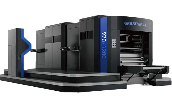
Die-cutting-line

Whether you’re working with film, paper, or light cartonboard, the core requirement is clean sheet separation at speed. In rotary converting, air entrainment and static are notorious for making sheets drift. This is why successful integrations always address the interface zone — the 300–500 mm right after the cutting nip where sheet control is most critical.

Step-by-Step: How to Integrate Stacking Without Breaking Your Production Flow

Integration doesn’t have to mean a complete line rebuild. A phased, methodical approach minimizes risk and keeps your current production running. Here’s a repeatable framework.

Step 1: Audit Your Current Delivery Characteristics

Start by documenting actual conditions at the delivery end over at least three different job types. Capture:

  • Sheet width, length, and caliper range.

  • Linear speed in meters per minute at the delivery conveyor.

  • Current pile quality (squareness deviation in mm, frequency of inter-sheet sticking).

  • Static charge levels measured with a field meter on exiting sheets.

This data is your baseline. Without it, you risk specifying a stacker that doesn’t match your material behavior. For converting operations that run multiple substrates — say, 300 g/m² folding carton in the morning and 50-micron label face stock in the afternoon — the sheet trajectory changes so dramatically that a one-setting-fits-all solution will not work. If your existing roll die cutting machine lacks process data logging, consider adding temporary sensors before you select any stacking system.

Step 2: Choose the Stacker Type Based on Your Product Mix

Not all stackers are created equal. The three most common configurations in rotary converting lines are:

Stacker Type Best For Speed Range Typical Integration Complexity
Pile stacker (vertical drop) Rigid sheets (paperboard, plastics >200 µm) Up to 150 m/min Low — often bolt-on
Shingle stacker (overlap stream) Flexible films, light labels, paper Up to 250 m/min Medium — requires precise overlap control
Robotic pick-and-place stacker Delicate surfaces, high-value outputs, special shapes Cycle-dependent High — needs vision and path programming

Most converters start their evaluation with a pile stacker because it handles the widest application window. However, if your throughput regularly crosses 200 m/min, an overlapping shingle system often becomes mandatory. At this stage, engaging with a supplier who can offer pre-configured integration packages designed for specific speed and material bands can save months of back-and-forth specification guesswork.

Step 3: Design the Mechanical and Electrical Interface

This is where many projects stall. The mechanical connection between a die cutter’s delivery frame and the stacker’s receiving conveyor must be designed to handle vibration, alignment tolerance, and accessibility for cleaning and maintenance. Key points:

  • Use a telescopic bridging conveyor with quick-release latches to allow rapid access to the die-cutting station for tooling changes.

  • Ensure the stacker’s control system accepts a master speed signal from the die cutter’s drive (typically via Ethernet/IP, Profinet, or analog 0–10 V) so that conveyor velocity, shingle overlap, and jogging frequency all scale automatically with line speed.

  • Plan for static dissipation. Even if your existing line “runs okay,” adding a longer sheet path changes triboelectric charging. Ionization bars should be positioned both at the receiving conveyor and directly above the stacking bin.

One frequent oversight is ignoring the floor plan flow. An inline stacker extends the line footprint by 3–6 meters. The stacking table must be accessible for forklift or pallet truck removal without interrupting the operator’s main aisle. Before you bolt anything down, run a spaghetti diagram of material and personnel movement for a full shift.

Step 4: Validate with the “Worst-Case” Job First

Once installed, run the most challenging product in your portfolio — the one with the lightest caliper, highest static, or most sensitive surface — at target production speed for at least two full hours. Measure:

  • Stack alignment deviation every 15 minutes (use a simple jig with a dial indicator).

  • Sheet count accuracy (compare stacker counter with a manual recount of 10 piles).

  • Marks or scuffs under oblique light inspection.

This validation protocol, ideally aligned with ISO 12647 or your own in-house standard, builds confidence and gives operators clear pass/fail criteria. If the stacker passes the worst-case test, every other job becomes routine. If your integration partner cannot demonstrate this level of process capability, you may need to explore alternative configurations that have already been validated across multiple substrates.

Common Pitfalls That Derail Integration (and How to Avoid Them)

Pitfall 1: Treating the stacker as an afterthought. Buying a stacker from a different generation of control technology than your die cutter — say, a modern drive-based cutter paired with an older relay-logic stacker — leads to perpetual communication glitches. Always match control platform eras or plan for a signal gateway.

Pitfall 2: Underestimating static behavior shift. A line that never had static issues can suddenly generate 25 kV of charge simply because the sheet path now includes an additional conveyor belt. Pre-emptive static testing with the exact materials is not optional.

Pitfall 3: Ignoring operator psychology. The best automation in the world fails if operators bypass it because it’s “too complicated” to change over. The human-machine interface on the stacker must share a common language with the die cutter’s HMI and allow job recipe storage for one-button recall. Operators need to trust that the machine stack is more precise than their manual stack, and this trust is built through transparent quality verification.

Making the Case: A Quick ROI Lens

Let’s look at a simplified scenario for a converting line producing 8,000,000 sheets per month:

  • Current state: Manual stacking limits speed to 70% of line capacity, producing 5.6 million sheets. Defect rate from handling is 4%. Operator cost per shift is consistent.

  • After integration: Line runs at 95% of capacity, producing 7.6 million sheets. Defect rate drops to 1%. Operator is reallocated to quality checks and pallet logistics.

The throughput gain alone often delivers a payback period of 9–15 months, even before factoring in reduced waste and injury risk. Specific payback varies with margin per sheet, so plug in your own numbers — the structure holds across most packaging and label segments.

From Integration to End-to-End Flow

Once the stacking system is running reliably, the next logical step is to couple it with automated palletizing or direct feed to a folder-gluer. The interface you’ve built now becomes a platform for successive automation. You’re no longer just solving a bottleneck; you’re building a digital, mechanized flow where sheets are touched by human hands only for quality audit, not for material transport.

If you’d like to explore what a fully harmonized system looks like — one where the converting unit, stacking module, and downstream logistics speak the same automation language — Changcheng’s integrated material handling solutions for the converting industry provide a pre-validated platform. Whether you are retrofitting an older roll die cutting machine or specifying a new line, starting from the delivery end often uncovers the most actionable improvement points in your entire finishing department.

A good integration doesn’t just replace an operator’s hands; it transforms the pace and predictability of your entire post-press flow. And that’s how you stop leaving margin at the delivery end.

Disclaimer: Performance figures and payback estimates are illustrative and based on typical converting environments. Actual results vary depending on product mix, material characteristics, and operational conditions. Always consult qualified engineering professionals for integration projects.

Slitting Terminology: Unwind, Rewind, Layboy

When Mike took over the family converting business, he thought the hardest part would be finance. But on his first shop-floor walk, the lead operator threw out a sentence that stopped him cold: “The unwind brake is hunting, the rewind is telescoping, and we’re stacking manually because the layboy jogger is out of sync.” Mike nodded as if he understood. He didn’t.

That afternoon, he pulled out the equipment manuals and quickly realized that these three words — unwind, rewind, and layboy — weren’t just jargon. They described the three fundamental stages that determine whether a converting line runs profitably or bleeds material through waste and downtime.

In this article, we’ll break down exactly what each term means, where things commonly go wrong, and what to look for if you’re evaluating new or upgraded equipment. If you’re currently mapping out a line for films, paper, or flexible packaging, you may want to explore modular configurations that address these three stages in one integrated system.

paper-slitting-machine

Unwind: The Starting Point of Any Converting Line

The unwind station does exactly what it sounds like — it holds the master roll and feeds material into the process at a controlled tension. But a “controlled tension” is where the art lies.

A basic unwind stand includes a shaft or chucking system (often pneumatic), a brake or motor, and a tension-sensing mechanism. In more advanced setups, you’ll find closed-loop tension control with load cells and an anti-vibration frame that compensates for out-of-round rolls.

The two most frequent unwind problems we see in the field:

  1. Tension spikes during roll changes. If the brake doesn’t stage properly or the inertia compensation is off, the sudden jerk can snap the web — especially on thin films below 12 microns.

  2. Telescoping at splice initiation. When operators don’t zero the dancer roller before splicing, the resulting slack creates lateral shifting that propagates all the way to the rewind.

From a specification standpoint, the unwind capacity (maximum roll diameter and weight), shaft type (air shaft vs. mechanical chuck), and tension range should match your thickest, heaviest material — not your average job. A processor running both 350-micron rigid PET and 9-micron CPP needs a drive capable of maintaining ±1% tension across that full range, which is where servo-driven unwinds with regenerative braking become a practical necessity rather than an upsell.

Rewind: More Than Just Winding Up

If unwind is about releasing material smoothly, rewind is about building a finished roll that won’t embarrass you at the customer’s site. The rewind station pulls the slit strips and winds them onto cores with a specific tension profile, often using a technique called taper tension.

Why does taper matter? As the roll diameter grows, the outer layers can crush the inner layers if tension stays constant. Taper gradually reduces winding tension as the roll builds, preventing crushed cores, starring, and telescoping. The formula most cited in industry references (based on principles from the TAPPI winding guidelines) ties the taper percentage to material modulus: high-modulus materials like PET tolerate less taper; extensible films like LDPE need a steeper taper curve.

A critical choice in rewind design is surface winding versus center winding. Surface (or drum) winding provides a more uniform roll density and excels at high speeds, but limits roll diameter. Center winding — where the core is directly driven — offers more flexibility for larger diameters and softer materials but requires extremely precise speed matching when running duplex or differential shafts. High-precision duplex rewind systems that can toggle between gap and contact winding modes give operators a practical way to switch between paper, film, and laminate without retooling for hours.

A common trap: operators often compensate for poor slitting blade condition by increasing rewind tension to “pull the strips straight.” This masks the root cause and leads to blocked rolls or customer complaints about baggy edges. If you’re adjusting taper every shift, check the blades first.

Layboy: The Unsung Hero of Sheet Delivery

Not every product ends up as a roll. When slitting lines convert paper, cartonboard, or certain films into sheets, the output needs to be stacked — and that’s where the layboy comes in.

A layboy (also called a sheet delivery or stacking station) receives cut sheets and arranges them into neat piles. It sounds simple, but at speeds above 150 m/min, sheet control becomes a real physics problem. The layboy typically includes a vacuum slowdown section, overlapping tape system, or air-flotation table to decelerate sheets without scratching them, followed by a jogger that aligns the stack.

The biggest misconception I encounter is that a layboy is just a passive “tray.” In reality, proper layboy setup affects downstream processes directly — uneven stacks jam automatic feeders in printing or packaging lines. One carton converter I spoke with reduced their customer rejects by 30% simply by upgrading to a layboy with servo-driven side joggers and a pallet lift that maintains a constant drop height.

For operations running both roll-to-roll and sheet-to-sheet products, the ability to add a layboy module to an existing slitting line — rather than buying a separate sheet cutter — can change the payback math entirely. Integrated stacking solutions that bridge roll and sheet delivery are becoming the norm in mid-volume converting houses that need flexibility without dedicating floor space to two machines.

Roll-to-roll-hot-stamping-machine

Common Mistakes and How to Avoid Them

Having walked through dozens of converting plants, here are the patterns I see repeatedly — and how to sidestep them:

  • Treating unwind, slitting, and rewind as independent settings. They form a closed loop. A tension change at unwind shifts the slit width slightly; a rewind speed adjustment affects the slitting blade entry angle. Always tune the entire line when changing materials.

  • Ignoring the taper curve until rolls telescope. If you’re setting taper as a single fixed percentage rather than a profile (e.g., 40% initial, ramping down to 20% at full diameter), you’re leaving yield on the table — especially on film grades prone to gauge-band buildup.

  • Skipping the layboy maintenance schedule. Worn slowdown belts, misaligned overlap rollers, and dirty jogger sensors are the top three causes of layboy-induced downtime. A 20-minute weekly checklist can prevent hours of lost production.

  • Overlooking operator training on terminology itself. When the team speaks a common language about unwind tension zones, rewind taper profiles, and layboy sequencing, troubleshooting conversations shift from “the machine is acting up” to “the unwind load cell needs recalibration” — and that precision saves time and money.

Bringing It All Together

Whether you’re running a single-station slitter that processes 300-mm-wide tape or a 2-meter-wide line for flexible packaging, these three stages — unwind, rewind, and layboy — are the architecture of your quality output. Understanding them doesn’t just make you fluent in converting terminology; it gives you a diagnostic framework you can use every day.

If you’re seeking a deeper level of control — where these stages are designed to work as a coordinated system rather than bolted-together components — Changcheng’s approach to integrating unwind, slitting, rewind, and layboy modules offers a practical reference point. Their engineering team starts each project by mapping the material’s modulus, gauge range, and downstream requirements before proposing a configuration, which aligns with the ISO 12643 safety standard for converting machinery and the kind of systematic selection process this article advocates. Get a tailored configuration proposal for your specific material and throughput targets.


Disclaimer: This article provides general guidance based on field experience and publicly available references such as TAPPI technical papers. Equipment specifications, tension profiles, and safety requirements vary by application. Always consult qualified engineers for selection and commissioning.

Single Knife vs Multiple Knife Slitting

The morning shift had just started when the line supervisor stared at the new job ticket: 0.12 mm aluminum foil, finished widths from 35 mm to 210 mm, a total of 18 strips. Last week’s single‑knife setup handled a similar order, but it took hours of repositioning. The multi‑knife arbor sitting on the rack could slit all strips in one pass — yet the team recalled the burr issues from the last time they tried it on ultra‑thin foil. This everyday dilemma repeats in converting plants, packaging facilities, and metal service centers worldwide. The choice between single knife and multiple knife slitting goes far beyond blade quantity; it touches on tension control, shaft rigidity, changeover time, and material behavior.

Before you decide on a new processing line, understanding these two core approaches becomes a crucial step. An investment in a complete coil slitting solution must align with your material spectrum and production goals.

The Basics of Slitting Geometry

Slitting is the longitudinal cutting of a master coil into narrower strips. A single knife system uses one upper and one lower blade pair, moving transversely across the web (or the web moves) to create each slit sequentially. A multiple knife system mounts a series of blade pairs on a common arbor or shaft, enabling all cuts to happen simultaneously. Both methods rely on shear cutting, razor cutting, or crush cutting depending on material type. A modern slitting machine often allows switching between these two modes with modular knife holders, but the underlying engineering constraints remain.

While the definitions are simple, the practical trade-offs are substantial. Let’s break them down across six dimensions that directly affect your output quality and cost per ton.

1. Changeover and Setup Time


Single knife systems excel when width changes are frequent but involve only one or two strips. Repositioning the blade carriage can be automated, but each new width adds cycle time. For a large number of strips, sequential cutting multiplies downtime. Multiple knife slitters, once set with spacers and blades for a given width combination, can produce dozens of strips in seconds. However, changing all knife positions for a new slitting recipe can be labor-intensive unless a cartridge or cassette system is used. According to a benchmark by the Association of International Metallizers and Coaters, converting a 10‑strip multi‑knife setup without quick‑change cartridges takes roughly 45 minutes, while a motorized single knife sled can shift between two‑strip orders in under 2 minutes.

2. Slitting Precision and Edge Quality


When a single blade pair engages the material, the side forces are relatively low, and the shear angle can be maintained precisely for each cut. This makes single knife slitting the go‑to for delicate films, thin foils (down to 5 µm), and high‑value materials where a single burr means rejection. Multiple knife systems must share the same arbor deflection. Even with high‑grade alloy shafts, the cumulative load may cause micron‑level sag, affecting the outermost strips differently than the center ones. Premium multi‑knife assemblies compensate via crowned arbors or hydraulic preloading, achieving tolerances of ±0.03 mm. Still, when slitting 1.5 µm capacitor film, many converters stick to single knife rewinding for absolute consistency.

paper-slitting-machine

3. Material Compatibility


Thick, rigid webs like 2 mm steel coil, heavy board, or abrasive materials favor the multi‑knife approach because the robust arbor absorbs cutting forces uniformly. Single knife slitting of thick materials suffers from slower speeds and the need to repeatedly re‑penetrate the edge, causing inconsistent side flow. Conversely, sticky or extensible materials like low‑density polyethylene and certain nonwovens benefit from the controlled, gentle single‑knife action that reduces edge welding. In the label industry, adhesive coating that fouls blades makes quick single‑knife changeover ideal, while mass production of paper‑based release liners runs efficiently on multi‑knife shear slitters.

4. Trim Waste and Yield


Multi‑knife slitting often produces a higher trim ratio during edge‑trim passes, but because it cuts all strips simultaneously, the overall scrap generation per ton can be lower for large runs. A single knife allows dynamic web guiding that can shift the slitting pattern to avoid defects, thus saving material. Real‑world data from a BOPP film plant showed that by switching from a fixed multi‑knife arrangement to an intelligent single‑knife line with defect mapping, edge waste dropped by 1.8%, translating to over $40,000 annual savings.

5. Speed and Throughput


Modern multiple knife slitters for light films can run at 800 m/min or higher because the cutting tools remain stationary. Single knife systems, limited by carriage dynamics and vibration, typically operate up to 300 m/min in production. For metal slitting lines, multiple knife arbors handle 200–300 m/min for thin gauge, while a single cold‑shear slitter rarely exceeds 80 m/min for repeat cuts. Therefore, if your business case relies on high‑volume standardized output, high-speed multi-knife slitting systems integrated with automatic tension control deliver unmatched efficiency.

6. Investment and Lifecycle Cost


The initial price of a single knife machine is attractive for startups or niche converters. However, scaling up with multiple single‑knife lines to match throughput may cost more in floor space and labor than one multi‑knife line. Multi‑knife slitters demand precision‑ground spacers, shear knives, and regular arbor inspection — maintenance costs run higher. A slitting machine designed for multi‑knife operation must factor in blade regrinding intervals, expected scrap rates, and labor. Industry standards, such as ISO 13953 for burr height control, provide a useful framework to evaluate quality consistency.

How to Make the Right Choice

Instead of asking “which is better,” focus on your production profile. Answer these questions:

  • Are your production batches typically less than 5,000 linear meters with frequent width changes? A single knife setup minimizes setup penalties.

  • Do you run the same four to twelve widths weekly with volumes exceeding 100,000 meters? Multiple knife slitting is your workhorse.

  • Is your material highly sensitive to edge deformation (e.g., battery separator film)? Lean toward single knife with active tension isolation.

  • Do you require just‑in‑time delivery of multiple narrow coils from a single master? The multi‑knife arbor becomes essential.

Often the optimal solution is a hybrid line: a multi‑knife slitting section for the bulk strips combined with a single slitting station for edge trimming or odd‑width strip. We’ve seen this configuration reduce total downtime by 35% in a copper foil facility processing both battery anode and flexible circuit materials. That plant integrated a custom slitting line layout where a quick‑swap arbor cartridge handled the repetitive widths, while a servo‑driven single knife trimmed the edges and cut the occasional non‑standard strip.

Bringing It Together

The choice between single knife and multiple knife slitting is not about the number of blades — it’s about matching the cutting physics to your material rheology, order pattern, and cost structure. In our experience working with hundreds of converters, the most successful ones don’t force one method to handle everything. They map their product portfolio against the strengths of each method and, when needed, adopt modular designs that accommodate both. Ultimately, the slitting machine you select must adapt to both current orders and future growth.

If you are evaluating a new system or upgrading an existing line, explore detailed slitting configurations that can be tailored to your specific films, foils, or metals. Our application engineers can help analyze your current scrap rates, changeover times, and target throughput to recommend whether a single, multi, or combined approach delivers the fastest payback.

Disclaimer: The cutting performance data cited are based on typical machine specifications and may vary depending on material properties and operating conditions. Always consult equipment manufacturers for feasibility trials.

Service & Support
  • One-year warranty
  • 24-hour online support
  • Remote diagnostics
p-l-10.webp
Your production line deserves a more efficient integration
Get a free customized connection solution

GET A QUOTE

0577-65664869

[email protected]

0
GET IN TOUCH NOW