The operator at the end of the converting line moves like a machine — but not the kind you want. Every few seconds, they twist, lift, align, and stack a pile of freshly die-cut sheets. The line was designed to run at 120 meters per minute, yet the real pace is set by human arms and attention spans. By mid-shift, stack heights drift, corners misalign, and the inevitable slowdown begins. If this scene sounds familiar, you’re staring at the single biggest hidden bottleneck in many finishing departments: manual sheet handling after rotary converting.
What makes this painful is that so much engineering has gone into precision cutting, registration, and web control, only to have the output arrive in a disorderly heap. The fix isn’t a faster operator; it’s removing the disconnect between the cutting unit and what happens next. A strategic integration of an automated sheet stacking system with your converting line can change the math — transforming an exhausted team’s end-of-shift scramble into orderly, clockable stacks ready for the next process.
Before diving into the how-to, it’s worth noting that not all finishing setups are ready to plug and play. If you’re seeking a deeply engineered approach that considers material behavior, line speed, and stacker architecture from the start, you might want to look at integrating a dedicated sheet stacking module with your converting line. But let’s first build a solid foundation on what this integration actually requires.
The Real Cost of Manual Stacking: More Than Labor
When managers calculate the cost of manual stacking, they often stop at wages. In reality, the hard numbers hide in three places:
-
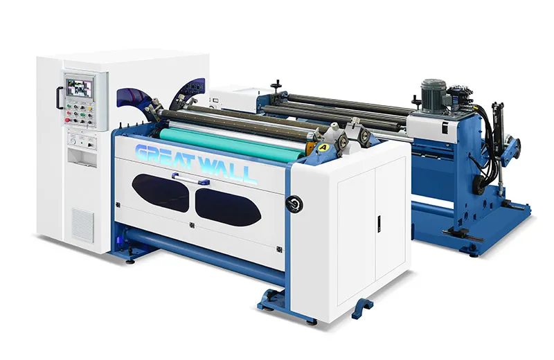
Micro-stops and speed caps. A modern roll die cutting machine can easily run at 150 meters per minute on thin cartonboard. Yet operators frequently dial down the speed to 80–100 m/min simply because they can’t keep up with stack changes or pile removal. Industry surveys from drupa trend reports indicate that up to 20% of available throughput is voluntarily sacrificed at the delivery end.
-
Quality rejections from handling damage. Finger pressure, dragging sheets across stacks, and uneven jogging all introduce scuffs, bent corners, and static-induced misalignment. In printed packaging converting, such defects can turn an entire pallet into rejected stock. Empirical observations from converting plants show that manual stacking-related defects typically account for 3–7% of total waste in high-speed lines.
-
Ergonomic churn and downtime. Repetitive lifting of stacks above 5 kg every 15–30 seconds is not sustainable. Injury rates climb, experienced operators drift to other departments, and replacement training adds hidden downtime. A targeted automation upgrade pays back not only in output per shift but in workforce stability.
These costs compound with job variety. Short runs with frequent stack changes exaggerate every inefficiency. Once you recognize the pattern, the question changes from “Can we afford automation?” to “Can we afford to keep manual stacking at full line speed?”
The Anatomy of an Integrated Stacking System
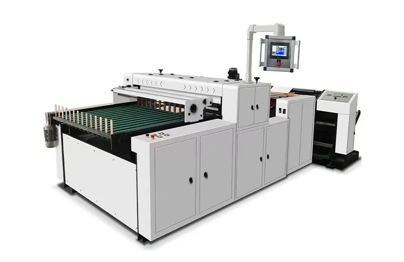
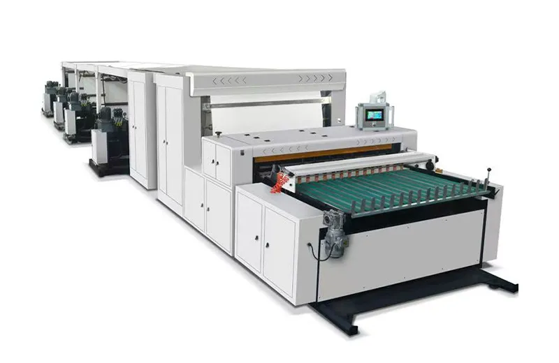
Before you can integrate, you need to know exactly what you’re integrating. A proper inline sheet stacking system is not simply a conveyor with a bin. It’s a synchronized set of modules that handle sheets from the moment they leave the die-cutting station until they’re counted, jogged, stacked, and presented for removal.
The key functional blocks typically include:
-
Receiving conveyor: Transfers sheets from the die unit’s delivery section, often with vacuum hold-down to maintain register.
-
Overlapping or shingling unit: Reduces sheet speed and creates an overlapping stream, which is gentler on delicate surfaces and essential for high-speed stability.
-
Alignment and jogging section: Uses side and back joggers with adjustable vibration frequency to square up each pile precisely. In advanced systems, this section also manages static elimination using active ionization bars.
-
Stacking table with automatic descending: The pile lowers as it builds, keeping the drop height constant to prevent sheet flutter and corner damage.
-
Batch counting and pile separation: Needle counters or optical sensors trigger separation sheets or pile ejection when a preset count is reached.
-
Outfeed for logistics: Integrates with pallet handling, conveyor outfeed, or robotic pick-and-place for direct palletizing.
Whether you’re working with film, paper, or light cartonboard, the core requirement is clean sheet separation at speed. In rotary converting, air entrainment and static are notorious for making sheets drift. This is why successful integrations always address the interface zone — the 300–500 mm right after the cutting nip where sheet control is most critical.
Step-by-Step: How to Integrate Stacking Without Breaking Your Production Flow
Integration doesn’t have to mean a complete line rebuild. A phased, methodical approach minimizes risk and keeps your current production running. Here’s a repeatable framework.
Step 1: Audit Your Current Delivery Characteristics
Start by documenting actual conditions at the delivery end over at least three different job types. Capture:
-
Sheet width, length, and caliper range.
-
Linear speed in meters per minute at the delivery conveyor.
-
Current pile quality (squareness deviation in mm, frequency of inter-sheet sticking).
-
Static charge levels measured with a field meter on exiting sheets.
This data is your baseline. Without it, you risk specifying a stacker that doesn’t match your material behavior. For converting operations that run multiple substrates — say, 300 g/m² folding carton in the morning and 50-micron label face stock in the afternoon — the sheet trajectory changes so dramatically that a one-setting-fits-all solution will not work. If your existing roll die cutting machine lacks process data logging, consider adding temporary sensors before you select any stacking system.
Step 2: Choose the Stacker Type Based on Your Product Mix
Not all stackers are created equal. The three most common configurations in rotary converting lines are:
| Stacker Type | Best For | Speed Range | Typical Integration Complexity |
|---|---|---|---|
| Pile stacker (vertical drop) | Rigid sheets (paperboard, plastics >200 µm) | Up to 150 m/min | Low — often bolt-on |
| Shingle stacker (overlap stream) | Flexible films, light labels, paper | Up to 250 m/min | Medium — requires precise overlap control |
| Robotic pick-and-place stacker | Delicate surfaces, high-value outputs, special shapes | Cycle-dependent | High — needs vision and path programming |
Most converters start their evaluation with a pile stacker because it handles the widest application window. However, if your throughput regularly crosses 200 m/min, an overlapping shingle system often becomes mandatory. At this stage, engaging with a supplier who can offer pre-configured integration packages designed for specific speed and material bands can save months of back-and-forth specification guesswork.
Step 3: Design the Mechanical and Electrical Interface
This is where many projects stall. The mechanical connection between a die cutter’s delivery frame and the stacker’s receiving conveyor must be designed to handle vibration, alignment tolerance, and accessibility for cleaning and maintenance. Key points:
-
Use a telescopic bridging conveyor with quick-release latches to allow rapid access to the die-cutting station for tooling changes.
-
Ensure the stacker’s control system accepts a master speed signal from the die cutter’s drive (typically via Ethernet/IP, Profinet, or analog 0–10 V) so that conveyor velocity, shingle overlap, and jogging frequency all scale automatically with line speed.
-
Plan for static dissipation. Even if your existing line “runs okay,” adding a longer sheet path changes triboelectric charging. Ionization bars should be positioned both at the receiving conveyor and directly above the stacking bin.
One frequent oversight is ignoring the floor plan flow. An inline stacker extends the line footprint by 3–6 meters. The stacking table must be accessible for forklift or pallet truck removal without interrupting the operator’s main aisle. Before you bolt anything down, run a spaghetti diagram of material and personnel movement for a full shift.
Step 4: Validate with the “Worst-Case” Job First
Once installed, run the most challenging product in your portfolio — the one with the lightest caliper, highest static, or most sensitive surface — at target production speed for at least two full hours. Measure:
-
Stack alignment deviation every 15 minutes (use a simple jig with a dial indicator).
-
Sheet count accuracy (compare stacker counter with a manual recount of 10 piles).
-
Marks or scuffs under oblique light inspection.
This validation protocol, ideally aligned with ISO 12647 or your own in-house standard, builds confidence and gives operators clear pass/fail criteria. If the stacker passes the worst-case test, every other job becomes routine. If your integration partner cannot demonstrate this level of process capability, you may need to explore alternative configurations that have already been validated across multiple substrates.
Common Pitfalls That Derail Integration (and How to Avoid Them)
Pitfall 1: Treating the stacker as an afterthought. Buying a stacker from a different generation of control technology than your die cutter — say, a modern drive-based cutter paired with an older relay-logic stacker — leads to perpetual communication glitches. Always match control platform eras or plan for a signal gateway.
Pitfall 2: Underestimating static behavior shift. A line that never had static issues can suddenly generate 25 kV of charge simply because the sheet path now includes an additional conveyor belt. Pre-emptive static testing with the exact materials is not optional.
Pitfall 3: Ignoring operator psychology. The best automation in the world fails if operators bypass it because it’s “too complicated” to change over. The human-machine interface on the stacker must share a common language with the die cutter’s HMI and allow job recipe storage for one-button recall. Operators need to trust that the machine stack is more precise than their manual stack, and this trust is built through transparent quality verification.
Making the Case: A Quick ROI Lens
Let’s look at a simplified scenario for a converting line producing 8,000,000 sheets per month:
-
Current state: Manual stacking limits speed to 70% of line capacity, producing 5.6 million sheets. Defect rate from handling is 4%. Operator cost per shift is consistent.
-
After integration: Line runs at 95% of capacity, producing 7.6 million sheets. Defect rate drops to 1%. Operator is reallocated to quality checks and pallet logistics.
The throughput gain alone often delivers a payback period of 9–15 months, even before factoring in reduced waste and injury risk. Specific payback varies with margin per sheet, so plug in your own numbers — the structure holds across most packaging and label segments.
From Integration to End-to-End Flow
Once the stacking system is running reliably, the next logical step is to couple it with automated palletizing or direct feed to a folder-gluer. The interface you’ve built now becomes a platform for successive automation. You’re no longer just solving a bottleneck; you’re building a digital, mechanized flow where sheets are touched by human hands only for quality audit, not for material transport.
If you’d like to explore what a fully harmonized system looks like — one where the converting unit, stacking module, and downstream logistics speak the same automation language — Changcheng’s integrated material handling solutions for the converting industry provide a pre-validated platform. Whether you are retrofitting an older roll die cutting machine or specifying a new line, starting from the delivery end often uncovers the most actionable improvement points in your entire finishing department.
A good integration doesn’t just replace an operator’s hands; it transforms the pace and predictability of your entire post-press flow. And that’s how you stop leaving margin at the delivery end.
Disclaimer: Performance figures and payback estimates are illustrative and based on typical converting environments. Actual results vary depending on product mix, material characteristics, and operational conditions. Always consult qualified engineering professionals for integration projects.