 English
 Español
 عربي
عربي When a single cross cutting station drifts by half a millimeter, the resulting scrap doesn’t just waste material. It cascades into missed delivery windows, brand rejection from CPG customers, and hours of troubleshooting that nobody budgeted for. I’ve stood on enough converting floors to know that registration errors are rarely caused by one dramatic failure. They’re the product of small, overlooked variables that compound until the line stops making good parts.
And here’s what frustrates production managers most: the machine can be mechanically sound, the operators experienced, and the tooling fresh, yet the cross cutting still wanders. That’s because registration accuracy isn’t a single adjustment—it’s a system behavior. Understanding where precision really comes from changes how you evaluate any rotary converting line.
If you’re responsible for a converting operation, seeing the full picture of what affects cross cutting registration will help you diagnose root causes faster and make smarter decisions when it’s time to upgrade your web handling infrastructure. A growing number of label and packaging specialists are finding that moving to a more integrated converting architecture eliminates several of these hidden variables at once.
Where Registration Errors Actually Begin
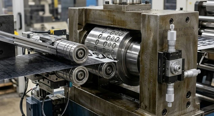
Most troubleshooting starts at the die. That’s logical, but often wrong. In my experience, the root cause sits upstream—in the way the web is delivered to the cutting station.
Web tension variability is the single biggest thief of registration accuracy. Polypropylene and thin PET films can elongate by 0.5% to 1.5% under normal processing tensions. When a tension spike of as little as 2–3 N occurs just before the die nip, the web stretches slightly, the cut lands in the wrong place, and the error is baked into the finished part. The operator adjusts the print-to-cut offset, the tension settles back, and now the next jobs are off in the opposite direction.
Mechanical backlash in the drive train is the second common culprit. Gear reducers, couplings, and timing belts all have clearance. On older rotary systems, cumulative backlash can exceed 0.05 mm at the die surface—enough to ruin small-format labels or blister pack lidding that demands ±0.1 mm tolerance. What makes backlash especially dangerous is that it’s load-dependent. The same machine that holds register perfectly during steady-state running may drift for the first 20 revolutions after a speed change or after splicing.
Material variability adds another layer. Recycled-content liners and bio-based films don’t behave like the uniform PET and BOPP grades that equipment was originally designed for. Moisture absorption, caliper variation across the web width, and inconsistent coefficient of friction all introduce micro-slippage at nip points. One technician I spoke with described chasing a 0.15 mm registration drift for three shifts, only to discover that the relative humidity in the plant had risen by 15% overnight, swelling the paper liner just enough to change the web path length.
These three factors—tension transients, mechanical lash, and material inconsistency—don’t take turns. They interact. A slight tension bump amplifies the effect of backlash. A humidity-change in the liner makes the tension control system hunt, which then excites mechanical resonance in the unwind stand. Registration accuracy isn’t lost in the die; it’s lost across the entire web path.
What the Spec Sheet Doesn’t Tell You
When you compare converting equipment datasheets, you’ll see registration accuracy listed as a single number—often ±0.1 mm or ±0.15 mm. That number tells you almost nothing about what you’ll experience on your floor with your materials.
The number that actually matters is registration stability over a production shift. A machine might hold ±0.08 mm on a 10-minute demonstration run with the manufacturer’s optimized material. Run it for eight hours on a 40-micron clear-on-clear film with intermittent adhesive zones, and the real-world performance can degrade to ±0.2 mm or worse if the tension control isn’t fast enough or the mechanical stiffness isn’t there.
FINAT, the international association for the label industry, has published technical guidelines that distinguish between short-term repeatability and long-term stability in converting accuracy. A system’s capability index (Cpk) often drops significantly when you evaluate it over 1,000+ cycles rather than 100. This is not a flaw in any particular brand—it’s a reflection of how hard it is to maintain thermal stability, lubrication consistency, and sensor calibration across hours of continuous operation.
Another spec-sheet blind spot is registration recovery after stop/start events. A machine that holds perfect register at constant speed may still produce scrap every time the line pauses for a splice change, a reject removal, or a roll change. The best converting systems handle these transients by maintaining tension on all critical spans even when the main drive is stationary, and by running a quick resynchronization routine on restart. If your current equipment doesn’t do this—or if the recovery logic relies on the operator manually re-phasing the die—you’re accepting waste that could be engineered out.
The Engineering Levers That Actually Move the Needle
If you want to raise cross cutting registration accuracy from “acceptable” to “bulletproof,” four design elements make the biggest difference. None of these are mysterious, but they’re expensive to implement and easy for some manufacturers to shortcut.
1. Closed-loop tension control at every section. Open-loop tension systems—where the drive simply outputs a torque command based on a preset dancer position—are too slow to react to real-world disturbances. The current benchmark in high-accuracy converting is a cascaded PID architecture running at 1 kHz or faster, fed by load cells that measure actual web tension at the roller, not just inferred from motor current. This lets the system catch a tension spike and correct it within 5–10 milliseconds, before the affected web segment reaches the cutting nip. When you’re running at 100 m/min, that’s the difference between 160 mm of scrap and zero.
2. Direct-drive rotary die stations with sub-arcminute positioning. The industry is steadily moving away from gear-driven die stations toward servo-coupled, direct-drive architectures. A well-designed servo-driven system eliminates multiple sources of mechanical backlash at once—no gearbox, no timing belt, no coupling windup. Resolution of 0.001° or better on the die shaft means you can command positional changes that are physically smaller than the elastic deformation of the substrate, which is the practical limit of what the process can achieve. When a facility is ready to explore this level of precision, evaluating a direct-drive rotary platform built for flexible films often reveals how much mechanical slop existed in the previous setup.
3. Temperature-compensated machine frames. It sounds arcane, but the difference in thermal expansion between steel and aluminum components inside a converting machine can produce a 0.02–0.04 mm registration shift over the course of a shift—just from the frame warming up. Leading manufacturers now use finite element analysis to place temperature sensors at strategic points and apply software-based compensation. This is one of those details you never think about until you’re running a 50-micron film at 120 m/min and can’t explain why register drifts every 45 minutes.
4. In-line vision with closed-loop feedback. Vision systems that only inspect finished parts are missing the point. The high-value application is placing a camera immediately after the die station and linking it directly to the registration controller. When the camera detects a drift of even 0.03 mm, the controller adjusts the phase offset automatically on the next revolution—no operator intervention, no accumulated error. According to a technical report from the Society of Manufacturing Engineers (SME), in-line closed-loop vision can reduce registration-related scrap by 40–60% compared to operator-dependent manual correction, simply by eliminating the delay between drift detection and correction.
How This Changes Your Equipment Evaluation Process
If you’re benchmarking converting equipment right now—or just trying to get more out of what you already own—here’s a practical framework.
Start by instrumenting your current line. A portable tension meter at the unwind, infeed, and outfeed positions will tell you in 30 minutes whether your tension control is the source of your registration headaches. If you see peak-to-peak variations exceeding 5% of setpoint, focus there first. No amount of die precision will compensate for a web that’s breathing.
Next, request a capability study that runs at least 5,000 consecutive cycles on your material, not the machine builder’s demo stock. Measure registration accuracy on both the leading edge and side lay, because many machines hold cross-web registration better than machine-direction registration—or vice versa—and you need to know which axis is the constraint.
Finally, ask potential suppliers about their approach to transient handling. How does the system manage tension during a splice? What’s the registration error on the first 10 parts after an E-stop reset? Good manufacturers will have data on this; great ones will show you the recovery scope traces from their own validation testing.
If you want to skip the piecemeal approach and work with a team that has already addressed these variables at a system level, it’s worth looking into Changcheng’s integrated converting solutions. Their engineering team treats registration accuracy as a web-path-wide challenge, not a die-station specification, and they routinely run capability studies on customer-supplied materials before commissioning. You can review the detailed machine configurations here and see whether the architecture matches what your toughest jobs demand.
References & Further Reading:
-
FINAT Technical Handbook, section on converting tolerances and test methods
-
SME Technical Paper TP18PUB144, “Advances in Closed-Loop Registration for Rotary Die Cutting”
-
ISO 12647-6: Graphic technology — Process control for the production of half-tone colour separations (principles relevant to print-to-cut alignment)
Disclaimer: This article is for informational purposes. Performance figures cited are based on publicly available guidelines and the author’s field experience; specific results depend on material, environment, and machine condition.